Let's recap the key requirements for the proper display of graphics:
- The Virtual Boy must show two distinct frames.
- Each frame has a resolution of 384x224 pixels.
- The colour palette consists of various shades of red, plus black/transparent (representing the LED in off state).
- The scenery requires parallax applied to achieve depth.
Good news is that all of this is accelerated by the Video Image Processor or 'VIP', a dedicated chip developed by Nintendo. It borrows some features from the old PPU, but I consider it a clear departure from its predecessors.
Architecture
At first glance, the VIP might appear to be just another tile engine, but it's much more advanced than that. For starters, it not only processes graphics data but also controls the scanner.
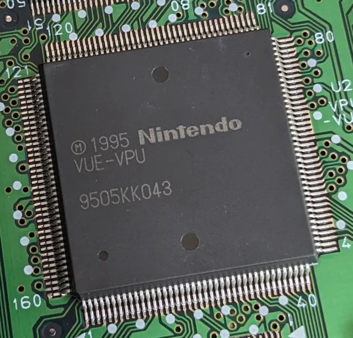
The VIP chip.
Moreover, whereas classic tile engines rendered graphics per scan line, the VIP employs a frame buffer architecture, storing the final frame in memory (as a bitmap) and then sending it for display. This is closer to the modus operandi of modern 3D renderers. In fact, the Virtual Boy went a step further by implementing a form of page flipping, in which two frame buffers are allocated per display unit, allowing the scanner to read from one while the VIP writes to the other. All of this helps to prevent image tearing.
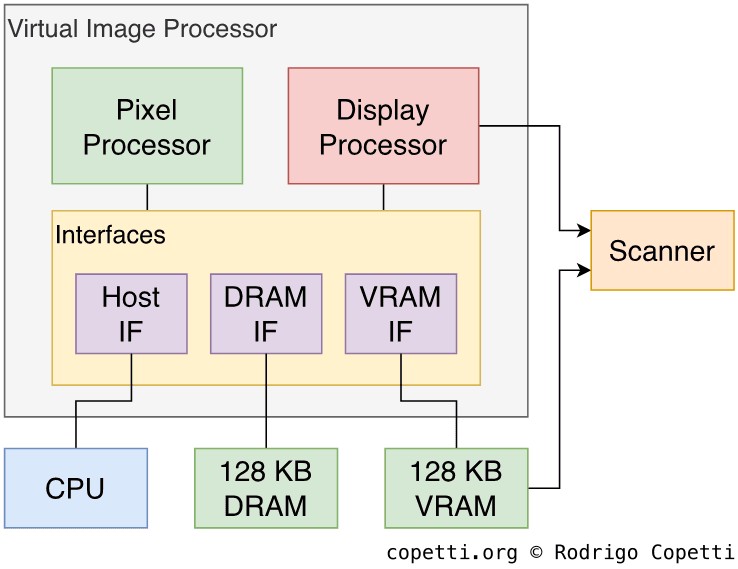
Architecture of the VIP.
Moving on, you can divide the VIP into three main areas:
- The Pixel Processor or 'XP': Generates backgrounds and sprites, much like the classic PPU. It writes the final processed bitmap to the frame buffer area in memory.
- The Display Processor or 'DP': Controls the scanner and sends a frame buffer for display.
- The interfaces: Provide access to two memory blocks - 128 KB of Video RAM (VRAM) and 128 KB of DRAM . The interfaces also arbitrate access between VRAM and the CPU (called the 'Host', from the VIP's perspective).
Overall, the pipeline is straightforward:
- The CPU sets up the VIP by writing to its internal registers and filling up VRAM and DRAM with the required materials.
- The XP then generates frame buffers, which are stored in VRAM.
- The DP selects the appropriate frame buffer and transmits it to the scanner for display. This is done by copying the frame, four columns at a time, into a small buffer area in VRAM known as Serial Access Memory or 'SAM', which is automatically broadcast to the scanner.
Organising the content
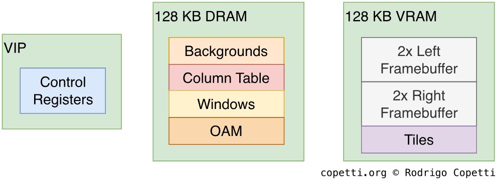
Memory layout of the VIP
From the developer's side, there are two blocks of memory used by the XP and DP:
- 128 KB of DRAM for storing graphics data to be processed.
- 128 KB of VRAM for storing the frame buffers accessed by the DP.
- As there are two display units, the system requires a total of four frame buffers. Each generated bitmap is 24 KB wide, so developers need to allocate 96 KB of memory. The remaining 32 KB is used by the XP to store tiles.
Notice that those 128 KB of VRAM are 'real' dual-ported DRAM , not merely a block of RAM reserved for graphics (which Nintendo also calls 'VRAM'). Dual-ported DRAM enables two devices to read from it at the same time, which explains why the XP can write to VRAM while the scanner is reading from it concurrently.
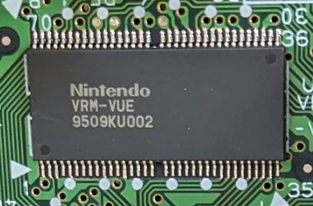
The VRAM chip.
Additionally, Nintendo fitted a particular VRAM chip that is nowhere to be found in any off-the-shelf catalogue. There is limited documentation about it, but according to details outlined in the patent application , Serial Access Memory (SAM) might be stored in a separate area within this chip. SAM is presumably made of Static RAM (SRAM) and contains extra circuitry that allows the scanner to pull 16 bits simultaneously .
Constructing a frame
Let's now dive deeper and see how a single frame is drawn on the Pixel Processor. To illustrate this, I'll borrow the assets of Virtual Boy Wario Land.
Before we start, I strongly recommend reading about a previous tile engine, as it will reinforce the old concepts.
Tiles

The pattern table with multiple tiles squashed together.

A single tile.
We have previously seen how traditional tile engines build their layers using 8x8 bitmaps. In the case of the Virtual Boy, tiles (originally called 'Characters') are stored in VRAM within an area known as the Pattern table. Each tile occupies 16 bytes (as 2 bits are allocated per pixel), so there is enough space for 2048 tiles.
In terms of colours, developers can compose eight colour palettes, four for background graphics and another four for sprites.
One may wonder about the purpose of colour palettes if the LEDs are monochrome. Well, this setup enables developers to use different shades of red. These shades are obtained by altering the brightness of the LEDs.
The brightness settings are stored in two registers, which are then referenced in the palettes, effectively creating a catalogue of different shades. All resulting palettes contain:
- Two custom reds.
- An additional red automatically calculated from the sum of the previous two.
- The 'transparent' colour.
Backgrounds
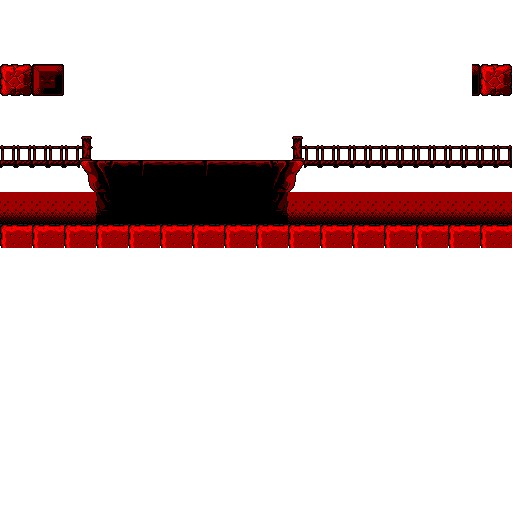
Background Layer 0 (BG0).
Background Layer 1 (BG1). This one is mostly hidden during gameplay, and then becomes fully visible when the game is paused.
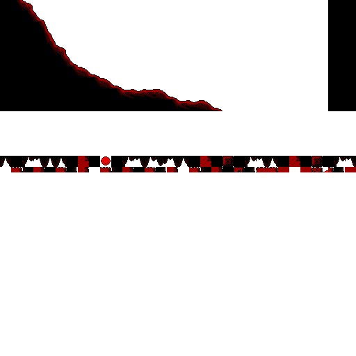
Background Layer 2 (BG2).
The background layer is very simple: tiles are selected to form a 512x512 map (64x64 tiles, resulting in 4096 tiles in total). But that's not all, because instead of having just a single background layer available... there are 14!
Each individual background layer is called a segment. A single segment occupies 8 KB of memory, with each tile reference storing horizontal/vertical flip attributes and a palette index. Each tile reference consumes 2 bytes of memory.
The Pixel Processor also supports combining multiple segments to generate a larger layer, although only certain combinations are available. The largest mix combines eight segments.
Sprites
Sprites (or 'Objects', as Nintendo calls them) are single tiles with independent coordinates, but they require more memory.
There is an area in DRAM called Object Attribute Memory (OAM) with 8 KB of allocated memory, in here sprites definitions are stored. Each definition occupies 8 bytes, allowing for up to 1024 sprites to be declared.
Each sprite includes the following properties:
- X and Y coordinates.
- A flag determining where it is displayed (left screen, right one, or both).
- The parallax offset, which applies automatic parallax. This makes each screen display the sprite with a slight horizontal shift.
- This value is signed: a positive value makes it look far away, whereas a negative value makes it appear closer.
- The index of the tile used.
- Horizontal/vertical flip.
- The palette index.
You'll notice there are no example screenshots included in this section; the following paragraphs explain why.
Window

World 1.
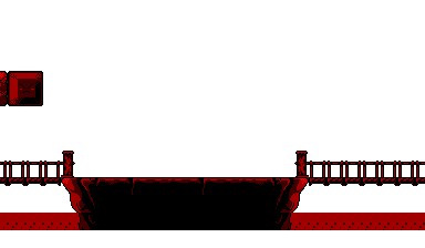
World 2. This one is rendered on both displays.
World 3. This one is expanded when the game is paused.

World 4. This is the 'sprite layer' I owe you from before.
The layering system may seem simple at first. After all, the VIP provides background layers and a sprite layer. So, what else would be needed?
In reality, to display any of the previously mentioned layers, they must be placed into a container called Window (also referred to as 'World'). A window is the actual plane that gets rendered to the screen, populated with layers previously constructed. There are 32 windows available which overlap to form the final frame, and each window definition occupies 32 bytes.
Windows provide various rendering modes. Developers can select a background or sprite layer and display it as it is. To do so, the window must be set to Normal mode or Object mode, depending on the layer type.
However, the chip offers additional modes that apply extra effects to background layers:
- Line Shift Mode: Individual rows of pixels can be shifted horizontally. This resembles the good ol' effects triggered during horizontal interrupts.
- Affine Mode: As the name indicates, this enables affine transformations! In other words, scaling, rotation, or a combination to simulate perspective projection .
Result
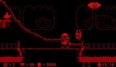
Tada!
After setting everything up, the Pixel Processor begins rendering the 32 windows. Once it is done, the final frame is placed in the frame buffer region. This process is then repeated for the other display unit as well.
Since the system employs a double-buffered design, the Display Processor always fetches the frame buffer that the Pixel Processor is not currently manipulating, preventing screen tearing. During the next active period, the Pixel Processor overwrites the frame previously displayed by the Display Processor, and the cycle continues.
If there is minimal content to render (i.e. only a few windows are used), there will be long gaps between writing to the frame buffer and the Display Processor retrieving it. This enables the CPU to make extra changes to the frame if needed. The VIP is also prepared for this: the CPU can set up interrupts to monitor various states of the VIP, including this scenario.
On the other hand, if too many affine windows are rendered, the Pixel Processor may miss the deadline, resulting in frame drops. Luckily, interrupts are available to detect this condition as well. In any case, the official documentation provided the timings for each layer type.
Creative content
As you can see, there is a lot more technology in this console than meets the eye.
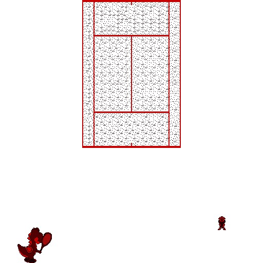
Initial background map.
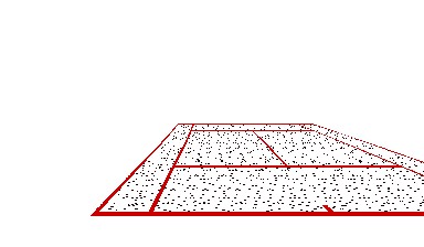
Rendered map, with perspective projection applied.
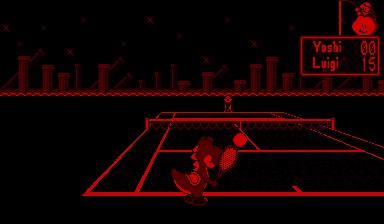
Frame seen by the user.
Initially, I believed the Game Boy Advance was the first portable console capable of reproducing the acclaimed Mode 7 effect from the Super Nintendo, nearly 11 years later. It turns out it was the Virtual Boy that achieved this first, just five years later. But it can go even further: as we've seen before, affine transformations on the Virtual Boy could be applied to all 32 layers (albeit with some limitations).
Furthermore, all these new functions operated in tandem with parallax effects, something that the VIP also took care of.
One can't help but wonder what kinds of games might have emerged had this console endured just a little longer, long enough for developers to get more comfortable with this hardware.
Another noteworthy feature was the CPU's ability to alter the frame buffer directly, providing developers with the flexibility to construct their own renderer when the VIP wasn't enough for them. This is what some games relied on to showcase their innovative graphics. For instance, Red Alarm implemented a scenery composed of 3D wireframes rendered by the CPU.
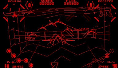
Red Alarm (1995).
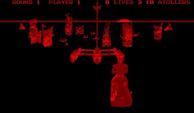
Waterworld (1995).
Unfortunately, fundamental challenges such as visible surface determination were not always addressed properly. I speculate this was due to the limitations of the CPU. In any case, this resulted in scenes turned into tangled meshes of elements, which made it difficult for the player to distinguish which objects were behind others.