To begin with, let's go over the physical screen of this console, which is where the user can appreciate everything that will be discussed in this section.
Display
The PSP carries a 4.3" TFT LCD screen. It has a resolution of 480x272 pixels (for reference, that's ~2.6 times the pixels of one screen of the Nintendo DS) and can display up to 16,777,216 colours. Thus, it's got a 24-bit colour depth (the so-called 'true color' scale).
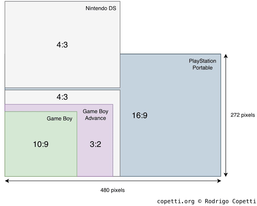
A comparison of screen resolution and aspect ratio between the Game Boy, Game Boy Advance, Nintendo DS, and PSP series.
The aspect ratio is almost 16:9, a format that was increasingly becoming standard on home televisions at the time. Notice that a wider range of view is also an opportunity for game designers to enhance the experience (especially in the first-person shooter genre).
Introducing the Graphics Engine
Now it's time to talk about the component in charge of producing pixels, the Graphics Engine (GE). The engine sits within the 'system group', making it effectively a 'group within a group'.
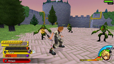
Kingdom Hearts Birth by Sleep (2010).
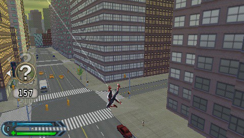
Spider-Man 3 (2007).
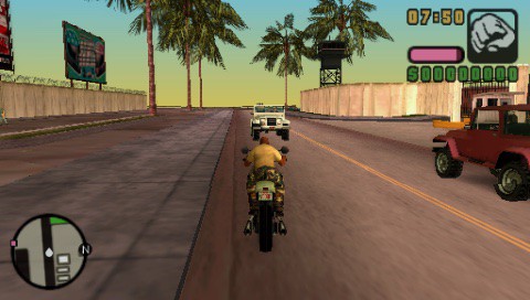
Grand Theft Auto: Vice City Stories (2006).
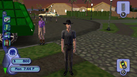
The Sims 2 (2005)
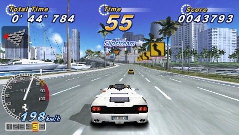
OutRun 2006: Coast 2 Coast (2006)

LocoRoco (2006)
The GE draws 3D graphics (polygons) with many features applied (e.g. texture mapping, lighting, and so much more), which you'll see in a bit.
Architecture of the Graphics Engine
The GE subsystem has lots of interesting quirks to mention, so this will be a very complex section. But fear not! I'll try to go step-by-step to avoid any confusion.
First things first, the GE is made of three components :
- The graphics core: where the actual graphics functionality happens.
- The eDRAM controller: mediates access between eDRAM memory and the core.
- The bus matrix: works as a 'bus arbiter' between the System Bus and the internals of the GE (remember the GE is found within the system group).
- In reality, this component is a mesh of wires with some logic, but for the sake of explaining, it's simpler to mask with a black box.
The reason for this design is that both main CPU and the graphics core can access those 2 MB of eDRAM. So, to prevent congestion, the traffic inside the GE goes through another Advanced High-performance Bus called local bus ('local' from the perspective of the GE). This allows the graphics core to perform its functions without depending on the System Bus to move data around (and consequently stalling the rest of the system).
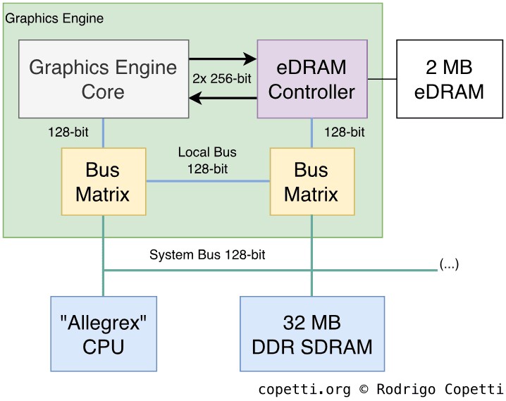
Architecture of the Graphics Engine.
The local bus is as wide as the System Bus (128 bits), but if that wasn't enough, the graphics core has a direct line to eDRAM using a 512-bit bus (made of two unidirectional 256-bit buses). You'll see why it's needed in the following section.
What about how the CPU and GE communicate with each other? As I said before, both CPU and graphics core can read from eDRAM. Additionally, the graphics core can access the System Bus to fetch data from any other component (including the main RAM). So, all of that just doesn't happen magically.
In a nutshell, two bus matrix blocks rewire the connection between the local bus and the System Bus. Whenever there's a component that wants to access an 'alien' bus, the bus matrices configure the communication so that one unit becomes master of the two buses and no other overlaps; this persists until the designated unit finishes transferring memory.
This behaviour reminds me of the commonly known technique called bus mastering, where the leading component is the 'bus master' and has complete control of the bus, and the rest are 'slaves' waiting for commands. However, I'm not sure which protocol or standard Sony's engineers were trying to replicate. Based on my understanding, I think it may be somewhat similar to I²C, a protocol used for serial communications (particularly useful with embedded systems) that also performs bus mastering.
Organising the content
Now that we've seen what components we've got and how they interact with each other, let's find out what information related to graphics we can place in memory.
There are three memory locations from which the GE will end up pulling or filling:
- 2 MB eDRAM: the aforementioned eDRAM. It's used to store the frame-buffer, z-buffer and texture buffer. Its contents are directly written by the GE. This memory space is also called 'local memory'.
- The CPU can access this memory if needed, although its speed is not ideal.
- 32 MB DDR SDRAM: this is the working area of the CPU for building display lists, vertex data, texture data and CLUTs (Colour lookup tables). In the context of graphics, this block is called 'host memory'.
- 16 KB SRAM: the scratchpad memory is also accessible by both CPU and GE.
Functionality
Like its home sibling, the PSP's graphics system focuses on rasterisation. However, the PSP's VRAM is half the size of the PS2's, and its bus is not as fast. To compensate, the PSP's Graphics Engine features a vector processor!
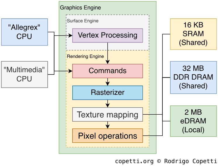
Pipeline design of the Graphics Engine.
I've skipped the interfaces since it's becoming too convoluted.
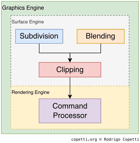
The graphics pipeline is very similar to that of the PS2, with the addition of the vector processing stage. The graphics core is divided into two areas: the surface engine, which deals with vector processing, and the rendering engine which, as its name indicates, performs rasterisation and effects .
Although its features have been explained in the past , the details of the graphics pipeline itself have not. The truth is, programmers don't depend on that information to build their games. However, for the sake of this analysis, I've deduced a model myself.
On another note, I've decided to make it a bit more technical than previous articles. I thought this would be a good opportunity to learn new concepts and have a wider vision of computing graphics. Having said that, I strongly recommend reading about the PS1 and PS2 graphics systems before continuing.
Commands
Command stage.
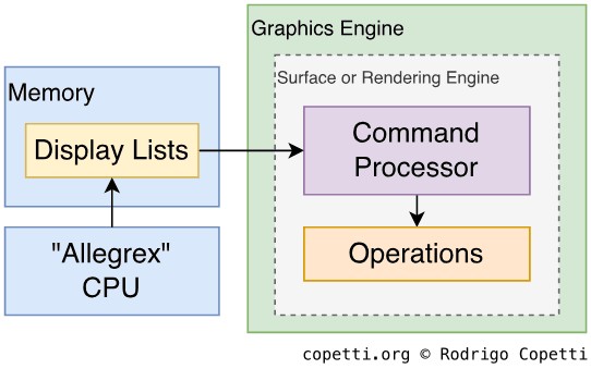
The Graphics Engine is controlled using traditional 'display lists' stored in main memory. The CPU builds them and the GPU reads them (using Direct Memory Access). Display lists basically tell the GPU what, how and where to draw. In the case of the PSP, display lists are not limited to rendering tasks - they can also include vector transformations.
The strategy implemented to process lists is critical to ensure that the CPU and GPU work concurrently and don't stall each other. Remember, we want the GPU to accelerate operations, not to be a burden. Hence, the CPU and GPU support deferred rendering , a technique that allows the CPU to build the next set of display lists while the GPU is processing a previous one. The GE is configured by specifying where in memory the display list starts (base address) and where it stops (stall address). As a result, there are two ways of allocating a list:
- Double buffered: there are two separate display lists areas. One is being transferred to the GPU, the other is being filled by the CPU. When both processors finish, they swap places.
- Store controlled: the CPU fills the same list the DMA unit is transferring to the CPU, but the CPU is some entries ahead to avoid overlapping. This uses less memory but it's susceptible to stalls if the GPU catches up.
Furthermore, the GPU's DMA unit is not just a 'dumb memory copier' - it can also understand the data transferred . Thus, display lists can include commands such as jump and return to tell the DMA to branch out and get data from somewhere else. This saves the CPU from embedding large resources (models, textures, etc.) in the display lists (which would effectively duplicate data in memory) and reduces bandwidth consumption. This system was inherited from the PS2.
Finally, the DMA can also interpret bounding box data: combined with information stored in the GE, the DMA will skip drawing commands that aren't within the display area. It's also possible to declare bounding boxes inside other bounding boxes, but let's leave that topic for another day!
Vector Processing
Vector Processing stage.
The Graphics Engine debuts the ability to perform operations over vectors, which helps to offload a lot of work from the CPU. Sony built this unit to accelerate common tasks previously carried out by the PS2's VPUs using microcode . While the GE is not as flexible as a VPU (the GE is a fixed-function unit), it does simplify a lot of coding (considering microcode had a considerable weight on the learning curve). The GE's vector processor is called surface engine.
The surface engine undertakes three types of task. The first is the operation of parametric surfaces . Remember the 'Infinite Worlds' section? Well, Sony explained that, while the PS2 was indeed capable of this, in the end just a few games bothered. It's possible that polygon performance, along with difficulty in design and implementation, were the main factors.
To tackle this, the surface engine implements two parametric curves:
- Bézier: a relatively fast function but its parameters change the global shape. Additionally, it suffers from 'continuity issues' which manifest as cracks on surfaces (discouraging its use with animations). It's often used for landscape generation.
- B-spline: requires more computations but fixes continuity issues and provides localised control. Character modelling and animation are potential candidates.
Both support levels of detail, which means that developers can set an arbitrary value to alter the level of subdivision (impacting the quality of the resulting model).
The second task is called vertex blending, a technique used for animations. The surface engine provides two types:
- Skinning (a.k.a. skeleton animation): movement relies on a structure of 'joints' attached to the character model. It's often applied for normal animation (walking, jumping, etc.).
- Morphing: uses multiple instances of a model and averages them to get a 'transition effect' (using linear interpolation). It's normally used for artificial animation (i.e. facial movement) and special effects. It comes with larger memory consumption and a steeper learning curve.
It's important to note that the CPU may still need to compute animations to process game logic (e.g. collision detection), so the CPU can't offload all the work.
Finally, the surface engine provides scissoring (discarding vertices outside the viewport/rectangular area) as well.
Rasterisation
Rasterising stage.
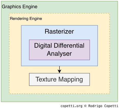
The next stage of graphics generation takes place in the rendering engine (skipping the command processor). In here, vector data is transformed into pixels, which is pretty much in pace with any other GPU in the market.
The engine draws many types of primitives, including points, lines, line strips, triangles, triangle strips, triangle fans and, finally, sprites (made of 2D rectangles). It also contains a unit called 'digital differential analyser' that will be used for interpolating values during rasterisation and texture mapping.
Developers can supply a projection matrix to apply perspective transformation. This sends their 3D world to a 2D space (so you can see it on the screen), using the virtual camera as a model. Modern features, like sub-pixel precision, are assumed to be implemented (otherwise, users would've been able to spot its absence right away).
Textures
Texture mapping stage.
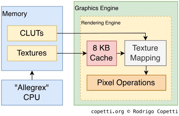
This may be the topic of most interest for some. Polygons (now mere pixels) can be painted with textures. At this stage, texture maps are fetched from memory and processed with many functions. This process is called texture mapping.
The rendering engine has three mapping modes or, in other words, three ways of processing texture maps:
- UV mapping: every coordinate of the model is mapped to a coordinate of the texture.
- Projective mapping: in a nutshell, it simulates a physical projector beaming a texture map onto a surface.
- Shade mapping: casts up to four lights (ambient, directional, point or spot) onto the model. This is useful when blending the result with another map (you'll see more in the next section).
- If programmers supply a texture map instead of a solid colour, the result is a 'fish eye' effect (useful for reflections, a.k.a. environmental mapping).
- This mode also permits toon shading.
Textures may use Colour Lookup Tables or 'CLUTs' to reduce their size. Furthermore, this engine applies perspective correction and bilinear or trilinear filtering for interpolation.
On another topic, there are 8 KB of texture cache found in the GE to save bandwidth. The cache employs the 'Least Recently Used' algorithm for space management.
Finally, while this pipeline is not programmable, developers can send extra colours to be blended with textures. There's also colour doubling (which doubles the RGB value of colours), colour addition (combines a primary colour with a secondary colour), and fogging (hazes distant polygons).
Pixel Operations
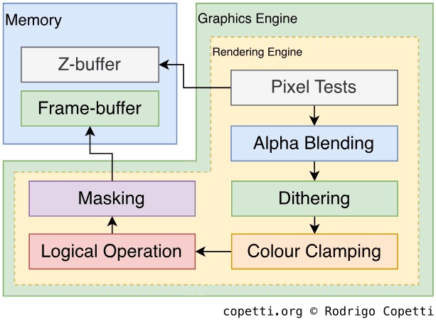
Pixel operation stage.
We're reaching the end of the pipeline. The initial geometry has been transformed into pixels, and these are now richly coloured, so it's time to decide what to do with them.
Some pixels may correspond to geometry that is not required for the current frame (for example, it may be occluded or masked). To filter these out, the GE can perform the following tests:
- Scissoring: discards polygons away from an arbitrary area.
- Depth range: discards too distant or too near polygons (developers set the reference values).
- Colour: discards pixels equal or not equal to an RGB value.
- Alpha: compares the pixel's alpha value to a reference value.
- Stencil: similar to alpha, but relies on the stencil value.
- Depth test: late Z-buffering.
Afterwards, pixels will also travel through these optional blocks for further effects:
- Alpha blending: combines non-opaque pixels with the ones in the frame-buffer using different arithmetic operators.
- Dithering: softens colour changes.
- Colour clamping: aligns RGB values to fit in the frame-buffer format.
- Logical operation: decides how to merge the new frame with the existing frame-buffer using logical operators (
AND,ORand many more). - Masking: as the name indicates, it masks the z-buffer or frame-buffer.
Complex functions like antialiasing are the result of a strategic combination of the above. Finally, the outputted pixel is written to the frame-buffer, which in turn is sent for display.
Observations
As evidenced, the PSP inherits various features from the PS2. The difference, however, is that much of this functionality is now hardwired into the silicon, as opposed to offering many general-purpose programmable units (which require manual setup). I presume this was done for two reasons: to use fewer transistors (so it fits in Tachyon and the board remains 'portable') and to facilitate the porting of PS2 codebases to the new console.
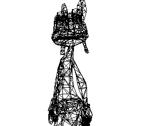
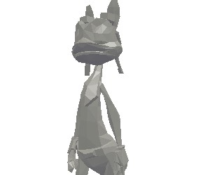
Model design
To show how this arrangement influenced model design, and to help compare it to the PS2 and Nintendo DS, here are two examples of models designed for the PSP.
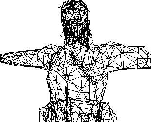
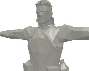
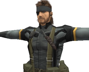
Interactive model available in the modern edition
Metal Gear Solid: Portable Ops Plus (2006).
1,383 triangles.

Interactive model available in the modern edition
Daxter (2006).
1,374 triangles.
Video out
The first model of this console (model '1000') has a proprietary video port called remote port at the bottom-left corner (next to the audio jack).
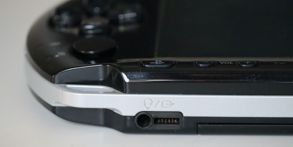
Bottom-right corner of the PSP (3000 model) showing the proprietary 'Video Out'.
The remote port uses the RS-232 protocol , an old standard for transferring data in serial. Though the specification wasn't publicly available to developers (let alone documented), a couple of audio headsets with control buttons appeared on the market. They apparently use the serial port to send commands (play, pause, etc.) to the console.
In later models ('2000' and '3000'), the remote port was expanded with an extra YCbCr pinout. Sony shipped three video cables (component, S-Video and composite) that rely on this interface to broadcast the PSP's screen to the TV.
The video cable sends a frame with a resolution of 720x480 pixels (in NTSC) or 720x576 pixels (in PAL), in either progressive or interlaced mode (the latter option is available only on the 3000 model). As the PSP's native resolution is 480x272 pixels, games show black bars to preserve their aspect ratio. However, these bars don't show when the console is running the 'XMB' visual shell, which natively supports adjusting its resolution according to the video cable.