Considering all the work done by the Emotion Engine, is there anything left? The last step, actually: Display!

Final Fantasy X (2001).
There's a simple but speedy chip specialised in this: the Graphics Synthesizer (GS) running at ~147.46 MHz . It contains 4 MB of DRAM embedded within it to do all processing in-house, thus removing the need to access the main memory. The embedded Dynamic RAM (eDRAM) is connected via separate buses based on the type of data needed.
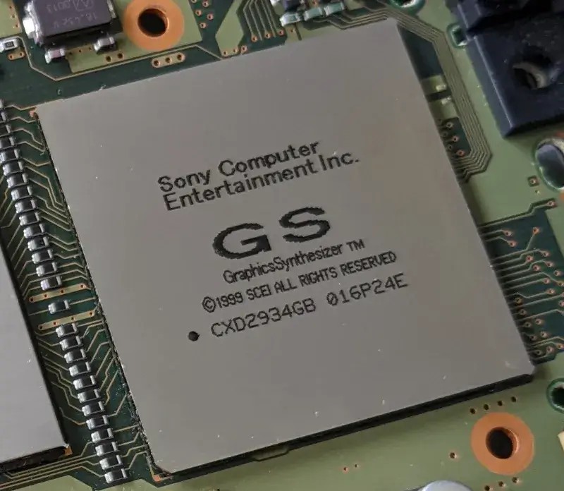
The Graphics Synthesizer chip on my motherboard.
The GS has fewer features than other graphics systems previously reviewed in this series. Nonetheless, it's very fast at what it does.
Architecture and design
This GPU only handles rasterisation and that is... generating pixels, mapping textures, applying lighting, and other effects. This means there are no vertex transformations (these are covered by the VPUs). Also, this is a fixed-function pipeline, so no fancy tweaking or shaders either: you are stuck with a fixed shading model (e.g. Gouraud).

Pipeline design of the Graphics Synthesizer.
It looks pretty simple, right? Well, let's dive deeper to see what happens at each stage.
Pre-Processing

Pre-Processing stage.
The Emotion Engine kick-starts the Graphics Synthesizer by filling its embedded DRAM with the required materials (Texture bitmaps and Colour Lookup Tables, the latter also known as 'CLUTs'), assigning values to the GS's registers to configure it, and finally issuing drawing commands (Display Lists) that instruct the GS to draw primitives (points, lines, triangles, sprites, etc.) at specific locations on the screen.
Additionally, the GS preprocesses some values that will be needed for later calculations. Most notably, it calculates the Digital Differential Algorithm value, which will be used for interpolation during drawing.
Rasterisation

Rasterising stage.
Using the values calculated previously, the rasteriser generates pixels from the primitives . This unit can concurrently generate 8 pixels with textures, or 16 pixels without. Each processed pixel carries the following values:
- RGBA: Corresponds to the gradient of Red, Green, Blue, and Alpha (transparency).
- Z-value: Used for depth testing in later stages.
- Fog: Optional, to simulate fog in the environment.
- Texture properties: Contains the address of the texture in DRAM and other properties (coordinates, level of detail, filter, etc.) that will be used in the next stage.
The rasteriser also performs Scissoring Tests to discard polygons outside the frame area (based on their X/Y values). Some pixel properties are forwarded to the 'Pixel testing' stage for further checks. Lighting is also provided by selecting one of the two choices available: Gouraud and Flat.
The resulting pack is then delivered to the 'Texture mapping' engine, but each property is operated by a specialised 'sub-engine', which enables the processing of different properties in parallel.
Texturing

Texture Mapping stage.
This stage is powered by a large Pixel Unit that can compute up to 16 pixels at a time. Here, textures are mapped onto the polygons (now pixels). Furthermore, fog and anti-aliasing effects can be applied as well.
Texture maps are fetched from DRAM in an area defined as Texture buffer, although this is interfaced by a separate area called Texture Page Buffer, which seems to serve as a caching mechanism for textures. CLUTs are also mapped using this page system. Both elements are retrieved through a 512-bit bus.
The Pixel Unit performs perspective correction to map textures onto the primitives (a significant improvement over the previous affine mapping approach). Moreover, it also provides bilinear and trilinear filtering, with the latter making use of mipmapped textures.
Testing

Pixel Testing stage.
Here, certain pixels are discarded if they don't meet several requirements, implemented as a series of tests:
- Alpha test: Compares a pixel's alpha value (transparency) against the 'standard' value. This is because, in some cases, the alpha value is required to fall within a certain range or greater/less than an arbitrary value.
- Destination Alpha test: Checks the pixel's alpha value again before drawing it to the frame buffer.
- Depth Test: Compares the pixel's Z-value against the corresponding Z-value in the Z-buffer. This avoids processing pixels that would otherwise be hidden behind other pixels.
Post-Processing

Post-Processing stage.
The last stage can apply some effects to our new pixels using the previous frame-buffer stored in local DRAM :
- Alpha Blending: Merges the colours of the current buffer with those of the previous one in memory.
- Dithering: Large RGBA values need to be trimmed, so dithering can be applied to soften the resulting loss of precision.
- Colour Clamping: After applying operations such as Alpha Blending, the new RGB value may exceed the valid range (0-255), so clamping sets the value within that range.
- Formatting: Converts the final frame-buffer generated by the pipeline into a format that can be stored in memory.
Finally, the new frame-buffer, along with the updated Z-buffer, is written to memory using a 1024-bit bus.
Even more post-processing
There's a dedicated component inside the GS called Programmable CRT Controller or 'PCRTC', which reads regions of the frame-buffer stored in memory and sends them through the video output , so you can see the frame on a TV. But that's not all: it also contains a special block called Merge Circuit that allows to alpha-blend two separate frame-buffers (useful if games want to reuse the previous frame to form the new one). The resulting frame can be output through the video signal and/or written back to memory.
Notice how this encoder has 'CRT' embedded within its name. Its inherent consequences are discussed at the end of this chapter.
Better models
With all that said, it's no surprise that game designers refreshed their character models to take advantage of smoother and more detailed surfaces. Take a look at this 'Before & After'.


Interactive model available in the modern edition
Crash Bandicoot (1996) for the PS1.
732 triangles.


Interactive model available in the modern edition
Crash Bandicoot: The Wrath of Cortex (2001).
2226 triangles.
Here are characters from new game series. These were modelled with high levels of detail from the ground up.


Interactive model available in the modern edition
Kingdom Hearts (2002).
2744 triangles.


Interactive model available in the modern edition
Dragon Quest VIII (2004).
2700 triangles.
It's worth mentioning that games like Dragon Quest implemented a custom lighting model known as Cel Shading (a term I have mentioned before). However, in my previous articles, I explained that the GPU was mainly responsible for this effect. In the PS2's case, the required colour calculations are presumably performed by the Emotion Engine, since the GS isn't as flexible as other GPUs.
Video Output
To recap, PCRTC sends the frame buffer through the video output signal. This is transmitted through a multi-purpose AV Multi Out socket, the exact interface found in the PS1.

The right side of the console , as seen from the rear. Showing A/C, Digital Audio, and AV Multi Out ports.
A significant change, however, is that the video encoder can now reuse the RGB pins to transfer a component signal (YCbCr) instead. This is activated by software through the system settings. Apart from the improvement in image quality, this allows PCRTC to output video beyond the standard interlaced PAL and NTSC dimensions.
The common bunch
Speaking of which, PCRTC can broadcast interlaced NTSC (480i), PAL (576i), and progressive NTSC only (480p).
But that's not all: PCRTC also supports VESA-compliant modes (offering up to 1280 x 1024-pixel resolutions) for use with a VGA adaptor (included with the Linux PS2 kit — I explain more in the 'Games' section). Be that as it may, the PS2's AV Multi Out didn't add any new pins for VESA, so it outputs the sync signal through the green wire, meaning that not all VGA monitors are compatible.
Ambitious resolutions
PCRTC also has an unusual mode that outputs 1080 interlaced scan-lines (1080i). Does that mean the PS2 can 'display HD'? Not in the modern/digital sense; it's far more constrained:
- The PS2 can't fit a full HD frame into its 4 MB of video memory, but the Graphics Synthesizer supports dynamic frame buffers, allowing a game to render any frame of virtually any size, provided the width is a multiple of 64 pixels. The height can be arbitrary. Games typically rendered frames close to NTSC dimensions to maintain acceptable performance.
- PCRTC operates independently and can crop or scale a frame to fit the chosen output dimensions. Since 1080i is an interlaced format, PCRTC only sends fields containing 540 scan-lines, each with up to 1920 samples.
- Widescreen frame-buffers are also expensive to render and, given their limited adoption, games resorted to anamorphic widescreen when supporting this aspect ratio.
- The European market was still affected by the common-denominator effect: PAL games often used letterboxing to conceal the unused horizontal lines and slowed down the refresh rate to comply with the 50 Hz standard. I call these bad ports.
To put this into practice, 1080i games such as Gran Turismo 4 rendered frames at 576 x 480 pixels, and instructed PCRTC to interlace its image. This effectively produced a 960i signal, which the game called '1080i'. You may like to know that Sony was, at the same time, selling premium 'HD' Trinitron CRTs that could display the extra scan-lines.
In any case, it's easy to see why 1080i saw limited adoption. Most game studios were unwilling to accept the performance penalty for a format that had yet to gain widespread popularity. In fact, this brings us to the next topic.
The stretching reality
So far, we've looked at the PS2's exceptional output modes, but what was the typical resolution used by games? The answer is... the small ones.
You see, when the Dreamcast debuted two years before, its GPU focused on unifying aspect ratios (using a common 640 x 480 resolution) and broadcasting full progressive-scan images (480p). These numbers were already part of the VGA protocol (used by computer monitors) and would later be favoured by emerging flat-panel TVs.
This did tax Holly, however. Consequently, when Sony designed the Graphics Synthesizer, the focus shifted towards image detail and frame rate. After all, 4 MB of Video RAM could only do so much.
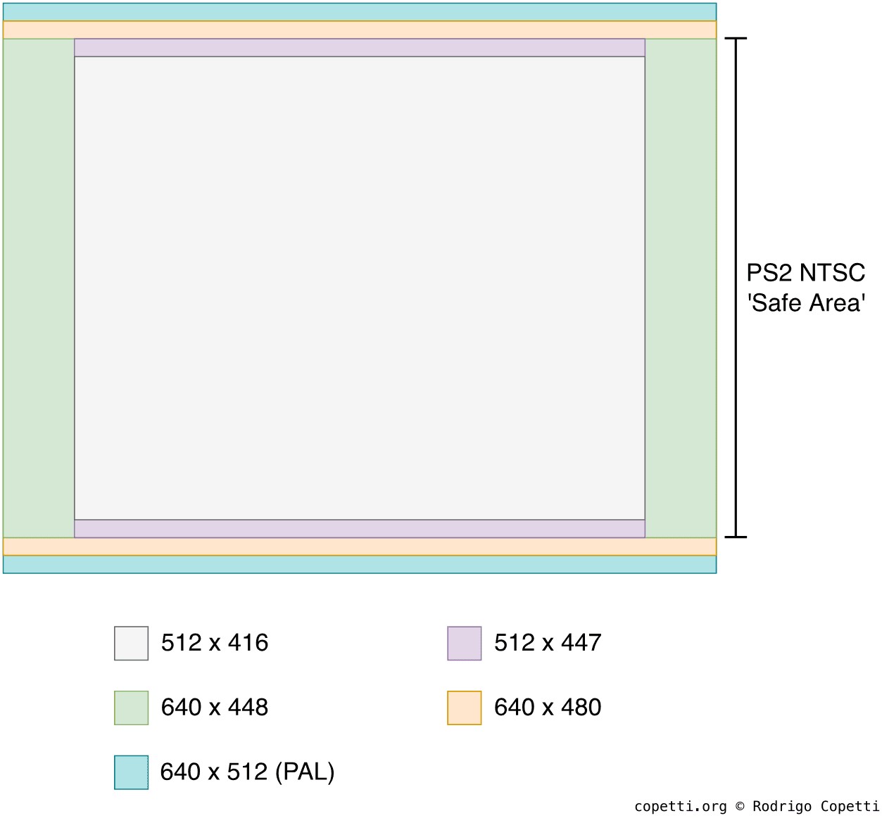
Comparison of different frame-buffer sizes used by games, marked against the NTSC safe area.
And so, PS2 games exhibited many of the same characteristics as those of the previous generation: varying resolutions, aspect ratios, and amounts of margin. To give you an idea:
- Final Fantasy X renders frames at 512 x 416 pixels.
- Crash Bandicoot: The Wrath of Cortex uses 640 x 448-pixel frames.
- Kingdom Hearts renders at 512 x 447 pixels.
Moreover, all of these games output interlaced video. When this happens, the GS provides two modes: either display the full frame across two fields, or one field per frame.
This trade-off was deemed acceptable because the imperfections of CRT displays helped disguise it. However, once LCD screens became the norm in the late noughties, these shortcomings became increasingly unpleasant. By then, though, Sony was already trying to push the all-digital PlayStation 3 (albeit with an absurd launch price).