The Neo Geo is the pinnacle of tile-based graphics, its richness of colours is comparable to frame-buffer-based systems (which only became affordable four years later). Be that as it may, when it comes to effects, the Super Nintendo has managed to do more with less.
Design
The graphics subsystem revolves around the typical Video Display Controller (VDC) model, but this time it is surrounded by a considerable number of components. The result is a console that can display tons of sprites - so many, in fact, that the iconic background layers are no longer relevant. This makes sense, as backgrounds were originally devised to tackle the limited number of sprites.
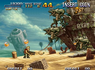
Metal Slug 3 (2000).
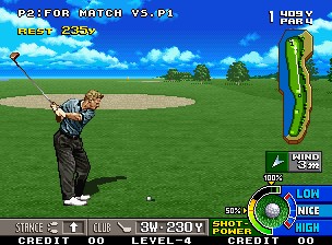
Neo Turf Masters (1996).
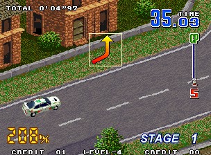
Neo Drift Out (1996).
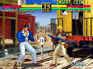
Art of Fighting 3: The Path of the Warrior (1996).
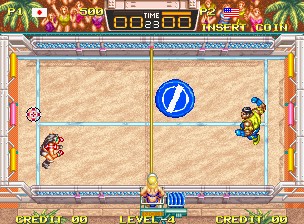
Windjammers (1993).
That being said, the console outputs a 240p signal. This embeds a frame with a dimension of 320 x 224 pixels (for NTSC) or 320 x 256 pixels (for PAL) .
Furthermore, thanks to its sophisticated video circuitry, the Neo Geo's output pixels are, among consoles of its generation, the closest to a perfect square .
The chipset
The group of chips in charge of drawing to the TV has evolved as new revisions were released. Over the years, SNK alternated between NEC and Fujitsu to manufacture their integrated circuits.
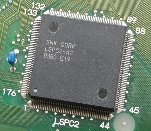
The 'LSPC-A2' chip.
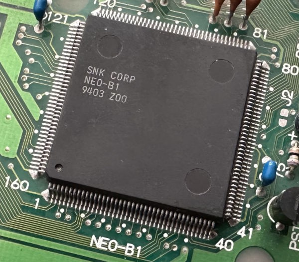
The 'NEO-B1' chip.
For explanatory purposes, let us start by describing the most notable chips in the set:
- The Motorola 68000. You already know it as the main CPU. Its main role is to fill the VRAM and Palette RAM; and set up the VDC (using a set of exposed registers).
- The Video Display Processor (VDC): Based on the information stored in multiple memory chips, it generates scan lines and sends them to 'Palette RAM', which will, in turn, generate the required colour pixels.
- The physical appearance of the VDC will vary depending on the motherboard model. For instance, the first revision housed three chips (the 'LSPC-A0', 'NEO-B0' and 'NEO-C0'), whereas later ones use a combination of the 'LSPC-A2' and the 'NEO-B1'.
- The Video DAC: Converts the colour stream received from 'Palette RAM' into a video signal.
Don't worry if the previous explanation is too dense. All of this will be explained more calmly in the following sections. Now, let's move on to analysing the information these chips operate on.
Organising the content
Graphics data is distributed across two separate boards. The first is the console's motherboard, and the other is found in the game cartridge. You may recall a similar arrangement implemented in the NES/Famicom.
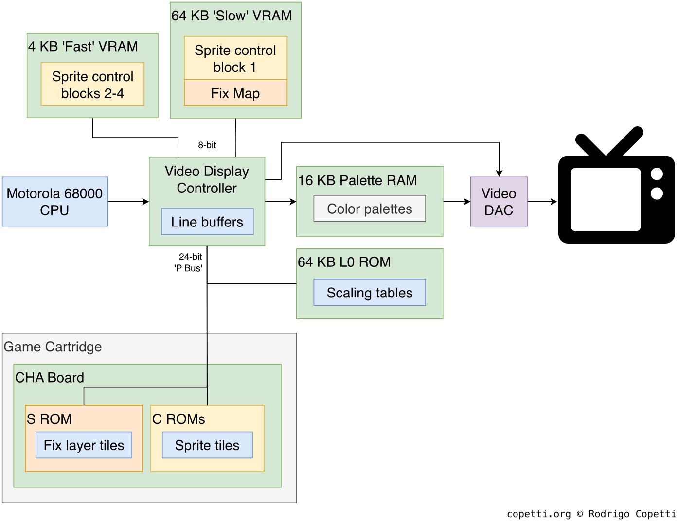
Memory architecture of the graphics subsystem
On the motherboard, we find:
- 68 KB of VRAM: Stores sprite attributes and tile references.
- Physically, VRAM is divided into 4 KB of 'Fast' VRAM and 64 KB of 'Slow' VRAM. Each is connected via a dedicated bus and exhibits drastically different latency. This conditions the number of cycles the CPU must wait after updating its content.
- Four line buffers: Store the scan lines rendered by the VDC. They only encode tile data that must be combined with other data in Palette RAM.
- 16 KB of Palette RAM: Stores the palettes of colours used by the graphics. This block is also tasked with sending pixel colours to the Video DAC.
- 64 KB of 'L0 ROM': It so happens the VDC can shrink sprites. To achieve this, the 'L0 ROM' stores lookup tables that tell the VDC which scan lines to render based on the zoom value requested. .
The corresponding board in the game cartridge is referred to as CHA Board and fits the following:
- Multiple C ROM chips: Store tiles for the Sprite Layer.
- An S ROM: Stores tiles for the 'Fix' Layer (I explain this layer in the next section).
Constructing the frame
Now that you've had a glance at the most important components, let me give you a quick summary of how the graphics subsystem turns data into an image - in other words, how it renders a frame:
- The CPU fills VRAM with the required references for the sprite layer and Fix layer.
- Based on the information in VRAM, the VDC fetches graphics from C ROMs and the S ROM, and stores them in the line buffers.
- While fetching occurs, the VDC uses the information in the line buffers to latch Palette RAM. This causes the latter to send colour pixel data to the Video DAC.
- The Video DAC outputs a video signal to the TV.
Based on these steps, let me provide a thorough explanation using Art of Fighting 3 as an example.
Tiles
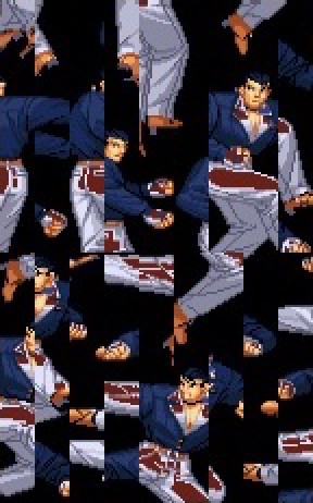
Various tiles.

A group of four tiles.
Traditionally known as 8 x 8 pixel bitmaps, tiles are the primary ingredient to build the graphics of the 4th generation. Due to its unique attributes, the Neo Geo only draws two types of graphics: fix tiles and sprites. Thus, tiles are encoded and stored separately depending on the graphic type. In both cases, each pixel is encoded using 4 bits (in other words, 4 bpp), meaning it can select up to 15 colours plus transparency.
In terms of colour composition, Palette RAM allows storing 256 colour palettes . Each palette is made of sixteen colours referencing 16-bit RGB values. Among all the available slots, there are two reserved entries: the 'Reference colour', which must be hardcoded to $8000 (pure black); and the 'Backdrop colour' which encodes an arbitrary colour that is displayed in the absence of tiles.
The CPU may update Palette RAM at any moment, but it should only do so during blanking periods. Otherwise, a snowing effect will appear.
Fixed plane
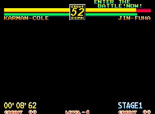
The Fixed plane with a black backdrop.
The Fixed plane is a layer 320 x 256 pixels (40 x 32 tiles) wide , pretty much the entire screen. Its displayed tiles are completely static and only have access to 16 colour palettes. In practice, this is used to display 'always-on' information, similar to the window layer of the Game Boy.
When broadcasted to a CRT screen, the displayed area will be smaller. Thus, its safe area is 38 x 28 tiles wide.
Fixed tiles are declared in a region of VRAM called Fix map. It takes the form of a 40 x 32 table, and each entry corresponds to a position on the screen.
The S ROM stores the exclusive tiles for the fixed plane in the cartridge. The VDC can only address up to 128 KB, but this limitation can be extended by bundling a mapper .
Sprites
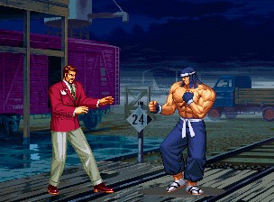
The Sprite layer, notice how it's used for all the areas of the scene (not just the two characters).
As you may know, sprites are freely moving tiles. Yet, in the case of the Neo Geo, the tiles used for sprites are exceptionally 16 x 16 pixels wide. With that in mind, the VDC can compose sprites ranging from 16 x 16 pixels (1 x 1 tiles) to 16 x 512 pixels (1 x 32 tiles). The reason for providing such tall compositions is that any sprite can also be combined horizontally by 'attaching' them to the previous one (though they still count as separate sprites). Overall, there is a limit of 96 sprites per scan line and 381 per frame , a large number compared to its competitors.
In terms of effects, sprites can be flipped and/or shrunk. These attributes are stored in the 'fast' block of VRAM, allowing the CPU to update them without considerable latency.
Due to their complexity, sprites are encoded in four areas in VRAM called Sprite Control Blocks (SCB), each of which stores the following attributes :
- SCB1: Tile reference, colour palette reference, auto animation, and X/Y flip.
- 'Auto animation' triggers an automatic tile reference increment every x frames (there are eight timings to choose from), which resets after 4 or 8 increments . This is useful for animating graphics without consuming CPU cycles.
- SCB2: Horizontal and vertical shrink.
- SCB3: Y position, vertical size (in terms of tiles) and whether the sprite is attached to the previous one.
- Sprite attachment causes the second sprite to inherit the predecessor's attributes, except for the horizontal shrink.
- SCB4: X position.
As you can see, for practical reasons, the last three blocks are stored in fast VRAM, while the first is stored in slow VRAM .
Result
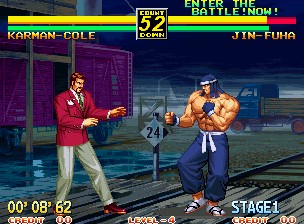
Resulting frame shown on the screen.
While competitors are known for rendering at the pace of the CRT beam, the Neo Geo implements a line buffer rendering system. With this approach, the console stores the rendered scan lines in the aforementioned buffer, rather than beaming them directly to the screen. Since the VDC incorporates enough memory for two scan lines, this allows the VDC to render one scan line while displaying the other, thereby enabling games to update graphics during active display (aside from H-Blank and V-Blank).
Truth be told, the VDC will still be accessing VRAM at the same time, so the CPU must wait between 12 and 16 cycles (depending on the operation) before accessing VRAM again; otherwise, the next operation will be ignored (hence the use of two VRAM variants).
Broadcasting the frame
To broadcast the rendered scan lines, the process varies depending on the console variant (AES or MVS).
The home model adds a video encoder to generate the composite and RGB signals. The A/V connector is somewhat similar to that of the Master System and MegaDrive, but is not interchangeable.
There is nothing of the sort in the MVS model, as the JAMMA protocol leaves that task to the cabinet's monitor. Thus, the motherboard sends a raw RGB plus sync signal.