The GPU package is a custom-made chip called Holly running at 100 MHz. Unlike previous in-house designs, Sega partnered with VideoLogic (now known as Imagination Technologies) to provide them with a competitive 3D accelerator.

The Holly chip (after removing the thermal pads) and the video encoder.
Inside Holly, we can find VideoLogic's exclusive graphics circuit: the PowerVR2 (also referred to as PowerVR Series2 and CLX2). It's based on their earlier PowerVR GPUs but specifically tailored for the Dreamcast.
Organising the content
8 MB of Video RAM (VRAM) are provided to store the materials that Holly needs to draw on the screen (e.g. textures, frame-buffers, commands, etc.) . The block is installed as four SDRAM chips using a 64-bit bus.
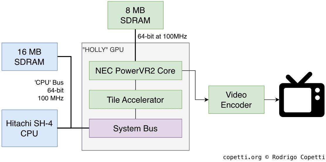
Architecture of Holly.
This memory is only accessed by Holly; the CPU fills it by talking to Holly or the Direct Memory Access (DMA) unit.
Architecture
VideoLogic chose an alternative approach to the construction of their 3D engine called Tile-Based Deferred Rendering (TBDR).
Instead of rendering a whole frame at once, as traditional Immediate Mode Renderers (IMRs) do , TBDR divides the rendering area into multiple sections called 'tiles'. It then carries out the rendering process on each tile individually, and the results are combined to form the final frame .

Sonic Adventure (1999).
This innovative design brings interesting advantages:
- It can be greatly parallelised, which significantly reduces bandwidth and power usage.
- It implements an elegant solution to the visibility problem by automatically sorting polygons from front to back and then performing z-tests at the first stages of the pipeline. The combination of these tasks not only solves the original issue, but also prevents overdraw (the rasterisation of hidden polygons), which wastes resources and degrades performance.
It's no surprise that Imagination took this efficient technology forward to build the Series 4 PowerVR cores, which powered a remarkable number of devices, including the first-generation iPhone, the Nokia N95, and the Dell Axim x51.
Construction
Let's take a look at the two main components of the Dreamcast's GPU :
Tile Accelerator
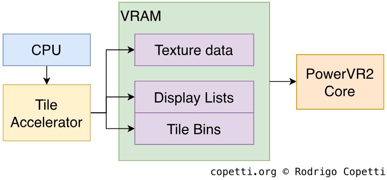
Architecture of the Tile Accelerator.
Before the rendering process begins, a component known as the Tile Accelerator (TA) performs pre-processing. It starts by allocating several 32 x 32 tile bins into which the geometry will be rendered.
Then, the Tile Accelerator:
- Grabs the geometry data and drawing commands issued by the CPU.
- Converts this data into an 'internal' format.
- Distributes the geometry to each bin according to its coordinates, discarding any clipped geometry.
- Generates the Display Lists, which instruct the subsequent components on how and where to draw the geometry.
The resulting Display Lists are then interpreted by the 3D engine: The PowerVR2.
PowerVR2 Core

Architecture of the PowerVR2 Core.
Here is where the graphics are brought to life. The Display Lists received from the TA tell the core to render the geometry of a single tile using an internal frame-buffer. The process is as follows:
- The Image Synthesis Processor (ISP) fetches the primitives (either triangles or quads) and performs Hidden-Surface Removal to remove unseen polygons. Then, after calculating its Z-buffers and stencil buffers, the data goes through Depth Testing to avoid rendering polygons that would appear behind others, and Stencil Tests to cull geometry that won't be visible if it lies behind a 2D polygon (also called Mask).
- Notice how these tests are effectively carried out at the start of the pipeline. In contrast, previous consoles using late z-buffering discard the geometry at the end of the pipeline. The ISP approach prevents processing the geometry that will ultimately be discarded , thereby saving resources.
- The Texture and Shading Processor (TSP) applies colouring, shading, and multiple effects across the tile area.
- Textures are not applied until the tile is exported, meaning that emerging overdraw (if any) will not reduce the fill rate.
Once the operation is complete, the rendered tile is written to the main frame-buffer in VRAM. This process is repeated until all tiles have been rendered. When the full frame is ready, the resulting frame-buffer is picked up by Holly and passed on to the Video encoder, which sends it through the standard video signal.
The big picture
Apart from the clear architectural difference, the Texture and Shading Processor comes with many capabilities that highlight the substantial leap this console makes over the old Saturn. Here are some notable examples:
- Alpha blending: Combines colours of overlapping layers to achieve transparency effects.
- The process used for applying transparency in this system is called order-independent transparency. The algorithm automatically sorts primitives before blending their colours, and while this slows down the rendering process, it removes the need for games to perform manual sorting. For this reason, Dreamcast titles excel at displaying transparent objects.
- When combined with the tile-based rendering system, order-independent transparency completely addresses earlier mishaps.
- Mip-mapping: Automatically selects a scaled-down version of the texture depending on the required level of detail. This is done to prevent processing large textures that appear far from the camera (which would be a waste of computation and would produce aliasing).
- Environment mapping: Applies reflections on textures.
- Bilinear, Trilinear, and anisotropic filtering: These are different algorithms used to smooth textures and reduce pixelation. They are ordered from 'worst' to 'best', with resulting quality directly proportional to the computational cost.
- This is a major improvement over the Saturn, which offered no texture filtering at all!
- Bump mapping: Simulates defects on surfaces without spending extra polygons.
- Vector Quantisation (VQ): A compression technique in which texture data is stored as pattern indices, reducing its size along the way . The processor decodes this format seamlessly, meaning there are no performance penalties .
Gaining detail
Holly can now draw roughly ten times more polygons than its predecessor. Here's a Before & After example that shows how model designs are no longer as constrained. I encourage you to take a closer look at them!


Interactive model available in the modern edition
Sonic R (1997) for the Saturn.
286 triangles (or 185 quadrilaterals).


Interactive model available in the modern edition
Sonic Adventure (1999) for the Dreamcast.
1001 triangles.
Video Output
There are two big milestones to unpack here. So, I've split this section into two parts.
The new standard
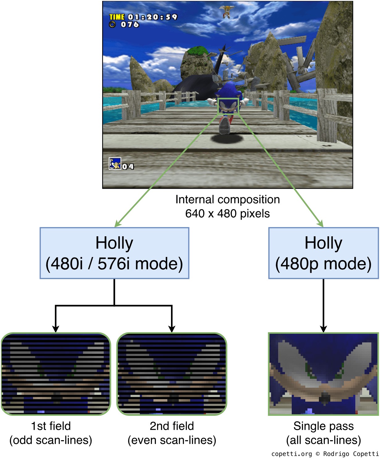
Representation of the different video output modes of Holly.
We've come a long way since consoles first began broadcasting 240p signals, a clever compromise between bandwidth and picture quality. Then, when 240 lines couldn't show enough, interlaced modes were introduced to increase detail without departing from the standard. Yet, the added flicker and lack of a common aspect ratio made it increasingly clear that PAL & NTSC standards were bottlenecking the imagery developers were striving for. Entering the fifth generation, you might expect the new power to turn into better video output, but instead found more inconsistency as 3D graphics battled for limited resources.
Well, for the first time in this series, Holly has managed to break through the PAL/NTSC barrier and deliver a modern format that games could actually use: 480 progressive scan-lines (also referred to as 480p or 31 kHz, due to the horizontal scan timings) - the same one adopted by computer VGA monitors.
For this reason, the Dreamcast's video system brings VGA qualities to TVs that may support it, with games typically rendering 640 x 480-pixel frame-buffers. Additionally, thanks to these dimensions, 1:1 pixel ratios finally became the norm.
Be that as it may, 480p does place additional strain on Holly, potentially reducing the frame rate and detail. To alleviate things, Holly offers to reduce the rendering resolution to 320 × 240 (Nintendo 64 style), and then upscale the output. However, it is prenominally useful for 2D arcade games.
Other capabilities included letterboxing to accommodate European games that don't use 576-pixel rows (which, to my knowledge, includes all of them).
The accompanying socket
To provide both modern and traditional signals, Sega fitted a unified socket that carries the following signal types:
- Composite: Combines the three signals needed for video (chroma, luma, and sync) into a single line, requiring only a one-pin cable.
- This format is used by old PAL and NTSC tellies with an RCA connection.
- S-Video: Separates the chroma signal from the combined signal, resulting in two video lines.
- RGB: Sends separate red, green, and blue signals, along with selectable sync types (composite sync, sync extracted from composite video, or sync extracted from S-Video).
- The SCART cable uses this format.
- VGA: Provides RGB with two dedicated sync signals (horizontal and vertical), resulting in five video lines in total. This is the only one that can output 480p.
- To use this output, Sega offered a VGA adaptor as an optional accessory.
- For some reason, the VGA output employs Digital Television (DTV) timings rather than VESA (as used by computer monitors) . This means that the Dreamcast sends a 720 × 480-pixel signal, of which only 640 pixel columns are utilised. If the display is not aware of this, it will interpret the signal as VESA, resulting in an undersampled, narrow, and blurred image.
Now, the Dreamcast can't encode all of these formats at the same time, so both the GPU and the audio processor contain a register named Image Mode. This coordinates which video and audio buses are activated to generate the requested output signal. The CPU detects the type of cable inserted by checking which 'select bits' on the video connector are active, then writes the appropriate values to the GPU. Finally, these values are forwarded to the audio processor.
Because VGA is strictly a progressive-scan format (as opposed to the traditional interlaced video), some compatibility issues arose with games designed exclusively for interlaced timings. Such games explicitly indicate in their code that they can't display on VGA, so the CPU displays an error screen until the user swaps the VGA cable with another type.